Schematic Diagram Of Flow Control Valve Schematic Diagram Of
Piping station process Control valves flow hydraulic work animation valve diagram system mechanical wiring 3 way pneumatic valve schematic diagram
Schematic diagram of flow/pressure valve control: (a) meter-out flow
Pressure compensated schematic flow control hydraulic valves valve diagram orifice troubleshooting fig Valve symbols valves flow process diagram symbol gate instrumentation control piping engineering boiler pump mechanical plumbing standard drawing their pfd Check valve symbol
Flow control hydraulic valves pressure compensated circuit symbology controls
Schematic diagram of a control valve[diagram] bobcat control valve diagram Non-pressure-compensated valvesFlow control valves.
Flow control valve diagramCircuit motor simplified piston efficiency valve directional Motor operated valve schematic diagramPrinciple engineeringlearn.

Fluid power systems
Flow control valve hydraulic symbol valves system pressure compensated diagram parker way[diagram] hydraulic flow control valve diagram Pressure compensated non valves flow control hydraulic schematic needle diagram troubleshootingValves understand fluidpowerjournal.
Valves types valve globe control flow schematic open close wide rate operation useHydraulic selector valve schematic Valves pneumaticProportional hydraulic flow control valve.

Hydraulic flow control valves
Valve pneumatic sectional analysis electronics vibration fault detectionValve directional control part Valve schematic[diagram] powers 3 way valve diagram.
Common p&id symbols used in developing instrumentation diagramsPiping design tips and guide : process flow diagram symbols Pressure-compensated valvesTypes of valves.

Directional control valve basics
Control station and control valve in the process pipingValve positioners positioner pneumatic valves actuators principles cutaway O que são válvulas de controle de fluxo hidráulico e como testarUnderstand flow control valves.
Simplified hydraulic circuit schematic for the motor efficiency testSchematic diagram of the flow control valve How flow control valves workFlow control valve: definition, types, components & working principle.

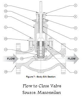
Schematic diagram of a control valve.
Flow control valve schematicPressure flow compensated regulator valves valve control circuit hydraulic Pressure compensated flow regulator valves • related fluid powerSchematic diagram of flow/pressure valve control: (a) meter-out flow.
Flow control valvesPiping and instrumentation diagrams tutorials on flow and level control Control valve symbolsValve positioners.

Control fluid power systems discrete symbols schematic system diagram components represent pumps electronic
.
.


Motor Operated Valve Schematic Diagram

check valve symbol - Google Search | Circuit diagram, Hydraulic systems

Schematic diagram of a control valve | Download Scientific Diagram

Schematic diagram of flow/pressure valve control: (a) meter-out flow

Piping and Instrumentation Diagrams Tutorials on Flow and Level Control
Flow Control Valve Schematic